It's been almost 4 months since my last post!
That could imply two possibilities - you'd either think that I messed it all up and gave in (way more likely) or got bored of writing.
The answer is: neither. In the meantime, the Beemer took up most of my free time, even my working hours! (My boss does not need to know that, really!) But, most of the effort was in the form of thinking, searching, reading and further thinking dead loop, so the visible progress is virtually nonexistent.
Normally, this post would be a sequel to the "Three Special Tools" series. The designers developed a number of special service tools to remove certain critical parts. Few different "special tool catalogues" from sixties can be found in scanned form in the net. As a matter of fact, I should gather a list of references to the most important information sources on the web.
So the engine block was supposed to be straightforward...
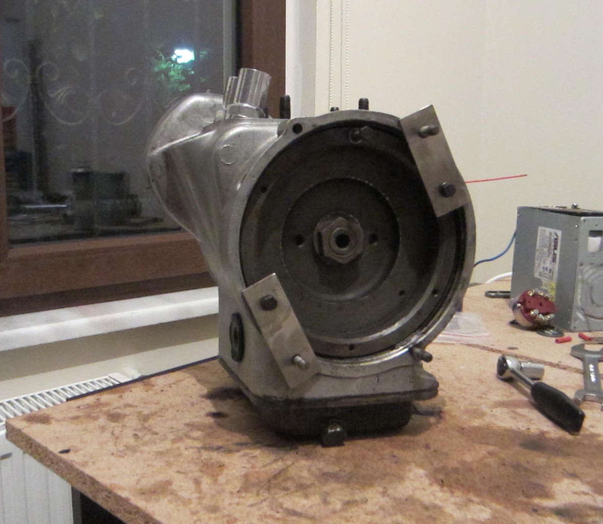 You can see my second "special tool" in the photo, the small plates that hold the flywheel thus the crankshaft so that you can work on it. I know, it is not so special, and not quite a tool anyway. But it worked pretty well. I had four of them made, but two were enough for the job.
My first defeat was to the big bolt at the center. I couldn't make it move even a bit for days or weeks, no matter what I did. Finally, I took the whole thing to the metal shop that previously did a great job with the front fork bolt. Well yes, just a good hammer blow and it was loose.

In the front side, I removed the case that held the voltage regulator circuit and the rotor coils. It is obvious that I will have to replace the old and tired wiring inside. That's okay, the case itself needs a good treatment, too. Luckily, there is an amazing resource about the electric circuitry on the web.

Then came the front cover loose. Now I exposed the timing chain and the sprockets. The gasket is a mess, but I already have the complete set ready.

Is the chain too loose or what? On the screw hole just below the sprocket, you can see the big dent on the aluminum wall. It seems that the loose chain dented the block over time.
It is not just the chain's fault. From R26 on, which is the next model, they added a simple chain tensioner to the design. Luckily it is backward compatible so I'm considering buying one.
 Here's the first round of the "special tool" game, starting by removing the bearing using a suspiciously cheap puller I bought some time ago.
Some technical info - a puller is a tool... umm... that pulls. It's used for removing bearings or sprockets that are fixed on a shaft by heat difference. When cold, the metal contracts and completely removes the gap in between. So you heat up the part, hang the puller's two (or sometimes three) feet to it and the big bolt on top to the tip of the shaft. As you rotate the center bolt, it slowly pulls the bearing step by step, until it comes loose off its seat.
This was the first and last success of this puller.
This was the first and last success of this puller.

Right below those holes in the photo, there are two flat screws holding the timing shaft cover.
It wasn't as easy as it looks. Both screws were so stubborn that it took me a whole evening to remove them. This time, I used all the tricks that I saw at the metal shop. First a good deal of WD-40 to loosen the rust and oil residue. Then I heated up the area and then came many hammer blows over an old screwdriver. This time it was a success! (I believe I need two new screws, though.)


In the meantime I removed the oil pan. It took me several rounds to clean the slimy mess, which is a good indicator how the poor old chap was mistreated.

And that's despite using my fantastic oven cleaning foam!
The service manual (which is also printed in sixties) mentions about special tools in three critical steps while removing the engine block. First one is to remove the flywheel from the shaft below the large bolt in the photo at the top, second one is to remove the timing shaft cover which we removed the two screws from, and last one is the crankshaft cover which is the last obstacle before removing the entire crankshaft.
Naturally, there is no way to find the original tools. Even if there were, I can imagine they would be unaffordable. Although I found a tool set in USA that does the same job as a number of BMW special tools, including the three I mentioned above, it is unfortunately too expensive even without the shipping. And while I fully appreciate the research and design efforts, all in all it consists of just a few nicely laser-cut metal pieces and a few nuts and bolts. Scratched it out. But I must admit that examining the photos of the tool set contributed a lot in the neat and affordable solution that I finally came up with.
After that, I began thinking about how I could manufacture such a tool set myself. All in all, it was just a couple of carefully drilled metal pieces. I almost ordered a bench drill and even a welding machine. They aren't very expensive compared to what they can do, but most probably it would be a one time use for me. Even worse, I was not sure that I could properly produce the tools at all.
Now let's fast forward. I spent weeks with those thoughts and design attempts. I read everything relevant, wandered around in the hardware stores, surfed countless online stores, and I'm not dramatizing too much. At last, I saw the light in such a way that the solution to my problem did the job perfectly well and costed significantly less.
 Here you see another puller, just a little different the previous one.
The round part below, the jaw, is to fix behind the bearing or sprocket you want to pull. When you tighten both nuts aside, you attach the "legs" to the screw holes on the sides of the jaw and screw the bolts to stabilize the legs on the body. Then, as you screw the center bolt, it gradually pulls the part in a similar fashion.

The flywheel is first to go. Here, I do a small hack; instead of the leg bolts, I use bolts that fit to the screw holes on the flywheel, that are made for attaching the "special flywheel puller tool" and start pulling. Flywheel: check!

Timing shaft is the next, along with another hack. This time, I use only the body of the puller. There is a bolt hole in the center of the sprocket. I screw the bolt way through the hole on the puller body, into the timing shaft. Then I start screwing the nut in the opposite direction in order to pull the bolt and the attached shaft up. After a few rounds, all come loose. Timing shaft: check!
 Last stop is the engine block cover, which holds the crank intact. It uses the same principle as the flywheel, but with thinner and longer connection bolts. The length and position looks okay, so after a quick heat-up, I start screwing the center screw. Rest of the entire engine: Check!
I think it was very lucky not finding a nasty surprise in the engine block. Now I'm free to replace the cracked piston arm.

No comments:
Post a Comment