Thursday, April 28, 2016

Last Stop

I feel that, in time I've gotten to proceed faster and with more self confidence. Wish I were able to be like this at the very beginning, but I believe that was the price to be paid - with a lot of time, reading and trial-and-error. 

Out of the three main systems, the final drive was the first to go. As I sorted out and closed up the engine block, and waiting for the rest of the parts to be painted, it became totally inevitable to move on to the transmission. After all, it has been sitting and waiting for my attention with extreme patience for more than a year now.

I hope you read about my disappointing "special tool" attempt to remove the centre nut of the output shaft. After a few more failures, I decided to go old school. Once again, using plenty of hot air, a hammer and chisel, I made it move. The rest was straightforward.

I had to go ahead and finish this up!


Next stop was the output flange. The engine output is transmitted over the shaft via a rubber "puck" between two identical flanges, this one and the one at the very front of the shaft. The flange sits on the shaft as a tight fit, so I need to find another trick to pull it off.

I tried with my cheapo puller first. Obviously didn't/couldn't work. Then a few more attempts mistreating my high quality bearing puller, which single handedly sorted out the entire engine block. That didn't work either - it was not a proper fit anyway. 

Lesson learned (again and again) - there is just one method and tool to do a job. Without the proper tool, you can't do it. This time, the lesson cost me a decent two armed good quality puller.

Can you notice my brand new "special tool"? The flange is designed for the rotational forces, but it can't bear the pulling. You can find examples of "folded" flanges in the internet. Therefore I supported it with a 22mm and two halves of a 20mm nut to resist bending. It was almost a perfect fit between the two tips.

Having fixed the puller behind the tips, I started rotating the puller bolt. It is an extremely stressful process, especially with all those squeaks and cracks coming out of the parts. It's always possible that another weak point could give up and bend or break instead of the puller breaking loose.

After a few careful turns, with a loud, metallic noise resembling a glass shattering, the flange finally got loose. 

That's it!

I don't expect any big blocking points anymore, but obviously a very thorough cleaning job  is awaiting me. And my brand new bearings and oil seals are ready. 

First, let's get rid of the nuts that are holding the cover. No, not that easy mister!


There are three bearings sitting inside of the cover. In order to get them loose, I needed - guess what - hot air again. At around 70-80C, the aluminum material expands just enough to give way to the steel bearings, which expand less.

No surprises inside. Plenty of dirt and mut leaking through the old seals, remains of old oil and six bearings one of which is shot.

Similarly, the rear (actually front) ends of the three shafts have bearings fitted to the transmission body. Again with enough heat, I got the shafts out of their beds.

There remains the gear shift mechanism. It's a very simple, compact yet very intelligent design. Let me try to explain...

The short shaft extending towards outside is attached to the gear shift pedal there. The circle next to it is for properly positioning the gear selectors.

Unlike cars, the bikes have sequential gearboxes. You can select 1, neutral, 2, 3, 4, etc. from bottom-up. You can only switch to the adjacent gears by strongly pressing the pedal upwards or downwards.

When you press the pedal, a fork rotates the selector circle a few centimeters. You can see the notches below that - they set the proper gear positions by sitting onto a metal tip. Currently it's in neutral. 1st notch is just to its left and 2, 3 and 4 are to the right. Simple, isn't it?

Here are the input and output shafts and the gear pairs for 4th, 3rd, 2nd and 1st from left to right. Output shaft (bottom) gears can rotate freely.

Two railed disks on the output shaft can move along the shaft. They have "dog teeth" pointing outwards on each side, so they can slide and attach to the desired gear and in neutral, both disks rest in the middle. If they ever attach to two gears at a time, you would simply smash the transmission. The gear selector circle avoids that with two properly positioned grooves on it.

The rest was easy... I washed every single part twice, pulled off the old bearings and fitted new ones, renewed the oil seals on the input, output, shift pedal and kickstarter shafts. Again heating up the cover, I then fit all three into their positions (you can't do it one by one) and heated up and closed the cover with the help of my rubber mallet.

While cleaning, I also sanded off the dull and rusty layer outside of the transmission body and treated it with metal polish.

It shouldn't be that difficult to fit the flange back onto the output shaft and attach the awkwardly shaped castle nut.


The rest should come easy...


Thursday, March 24, 2016

Electrics...

The engine is ready, the body is being painted and I'm left with my unsuccessful "special tool" attempts to open up the transmission. I thought I'd better give it a break so I took on the generator. You can find priceless literature on the net about the electrics, just like any other component.

The generator consists of the simplest electrical components and produces a maximum power of mere 60 Watts. For comparison, my 2008 BMW F650GS produces 400 Watts. A modern nay regular headlight bulb needs 55 Watts. I do want to clean it up a bit, but my main purpose is to understand how it actually works - call it "professional interest"...

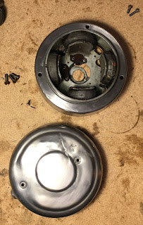
It's very easy to produce electric. You just need to rotate a wire loop in a magnetic field fast enough to create electric field and that induces the current in the conductor, which is the rotor windings on the right in the photo above. The rest of the system simply limits this uncontrolled electric current within the operating range of the system and ignites a spark in the plug in the right time. 

So where's the magnetic field then? It's easy, too - if you don't have a real magnet, wind a wire around an iron core and apply electric. Here - you made an electromagnet. This is the rear side of the generator, the four windings on the sides are connected to the battery, they are our electromagnets.

The rotor sits right in the middle of them and uses the magnetic field they create. The disadvantage of this setup is that if you run out of battery, zou can't jump start the engine.

The R25/3 was the low end model, possibly therefore they chose a cheaper and more compact system instead of having a real magnet. By the way, look at the poor state of the paint.

Let's remove the parts one by one. First the plate on top, held by two screws. This is responsible of the ignition timing. Think about it how you would push your legs when swinging; the spark must be ignited at the right time, in synchronization with the compression cycle of the air-fuel mixture so that the energy created by this "mini explosion" adds up to the next cycle.

The timer rotating above the center hole touches the conductive pin every half cycle and causes a spark. You actually need a spark every two revolutions, so three out of four sparks are wasted but this makes the system so much simpler. The pin sits on a little arm with a spring on it, which is an "emergency valve" to safely discharge in case of an overload. 
The two so-called brushes collect the electric generated in the rotor. They are pressed onto the rotor contacts with two little springs behind them. The generated electric then goes to another electromagnet, which limits the current to protect the battery and bulbs. And it does that only with a mechanical switch. When the voltage rises, it pulls the switch off and cuts off the system. When it falls again, it switches back on. And it does that very fast and continuously. Just imagine yourself controlling the lamp in your living room that way! 

It's fairly dirty inside, as I remove I also try to clean them but it is not easy with all these tiny details. As all the components were removed, I took the entire body in spite of the electromagnet windings and soaked in detergent water and dried using the hot air gun. Still not clean enough, though.

This is a high voltage transformer, connected to the spark plug via the soldered wire in the middle.

When the timer touches the pin, it transforms the 6-7 Volts on one side up to something like 15-20 thousand Volts for a fraction of a second and feeds to the spark plug. The spark plug is just two electrodes separated by 0,6 millimeters of distance. The high voltage is able to jump this distance, thus creates a spark between them to ignite the already compressed air-fuel mixture. 

As I remove, I renew some of the old and tired cables.
After the cleaning, I begin to sand the cover and body. It's a hard job, but the principle is so simple and extremely effective. You take a few different "grit" sandpapers, soak them in water and apply starting with the coarse (smaller grit) and proceed with finer. The result is good.

The generator body is steel and has to be painted but I decided to leave the aluminium cover as it is. It isn't possible to undo the scars on the cover anymore, time is cruel to all of us.
After a good enough weekend for the paint job, it's now time to bring it all back together. 

This is the front end of the crankshaft. A "woodruff key" fits into the notch on it. The spline on the inner face of the rotor slides onto the key and avoids any slippage while rotating. 
The rotor sits into its place with one or two mallet blows. 

I found a pleasant detail that I didn't notice while removing. The ignition timing adjustment is usually a tricky job with a special device. Luckily, this one has a notch on the timer so it can only sit in one position relative to the rotor. So I only have to make some fine tuning, if at all.
Screwing the body onto the engine and attached the timer with the center bolt. New screws, new plastics, partially new cables...
There is one last adjustment to make. The gap at the tip of the "emergency valve" I mentioned above (that is not a scientific name, I made it up) needs to be 0,4 millimeters wide. It is just a screw adjusted by loosening and tightening a nut each side. I adjust the gap and check with the feeler gauge. Done.
And last but not least, the front cover. I will need to open it again to connect the wiring harness, but until then better keep it tidy. I feel more and more energized and motivated as the old and tired parts get together again, much cleaner, much brighter and much fitter. Looks beautiful! What's left is just the wheels and the transmission that I still couldn't open yet. The end is near...


Wednesday, February 24, 2016

Closing Up...

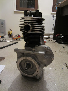
I decided to take my chance with the relatively mild weather last week. It has been a very impatient wait, as this paint job was also blocking my progress on the engine. So I finally took a can of heat resistant black spray paint and painted the cylinder block and the oil pan. Unfortunately it was a bit too chilly and windy, so I cannot call it excellent. 

I don't have any photos during the paint, unfortunately. I hurried up to complete the job before the weather gets worse.

Not that bad, really. I waited the paint to dry and carefully hammered the pushrod guides into their slots. I also replaced the rubber grommets. 


Then came the piston. You can notice the three metal rings around it. They act as the only insulator between the hot, messy combustion chamber and clean, tidy and oily engine body. They reduce the gap in between the piston and the cylinder wall to virtually zero, therefore the combustion chamber can preserve its high pressure, while the cylinder wall is lubricated by the oil below.

The ring brace in the photo is used for squeezing the piston rings in order to fit the piston into the cylinder. 
I put the piston inside the cylinder and tighten the bolt using the provided square key. When it's fully tightened, I carefully aligned it onto the cylinder and slid into it. After a few tries, the piston ended up where it always belonged to.


Using up my brand new gasket set...


Getting here was hard. The following needed to be done at the same time:
- Hold the cylinder head, which is fairly heavy, above the piston rod opening 
- Align the piston fitting holes to the tip of the piston rod below
- Hammer the bushing into the fitting holes to fix the piston to the rod
- Put the spring into the end of the fitting hole to trap the bushing
- In the meantime, do not let the piston slide too low to let the rings loose out of the cylinder

If you counted the hands needed, you'd have noticed that you'd need more than two for all of these. Luckily, I've got a skilled assistant for such situations.

The top surface of the piston is quite scratchy, but the sides matter more. It should be fine.

Now it's time to fit the cam chain. I think I explained the relationsip between the large "crankshaft" at the center and the "camshaft" at top right of it. The cranksahft moves the piston up and down, while the camshaft opens and closes the intake and exhaust valves. For two full turns of the crankshaft, the camshaft makes one turn. 

This is the most critical part of the whole engine - the two shafts must be so aligned, that the valves and the piston is properly synchronized. If not, my best bet will be a weak and noisy engine with too much fuel consumption. Worst (and more likely) case is that many parts of the engine will go beyond any repair.


The valve timings are specified in the service manual in degrees relative to the "top dead center", where the piston reaches the topmost point. I prepared a dial according to the information and attached to the center of the crankshaft. It needed a couple of tries until I get the correct synchronization.


I attached the chain clip and then screwed in the chain tensioner and its spring that I bought recently in Germany. (just behind the crankshaft in the photo) This is not part of the original design, but rather an improvement introduced with the later model R27 - and completely backward compatible with R25, too. I mentioned about the old slack chain having damaged its surroundings, now I feel better with the tensioner. 

After oiling the paper gasket, I closed the front cover with brand new bolts as usual.

I can close the cylinder now. Putting its new gasket, I put the header block and place the cams on their places. The camshaft has two "rockers" which control opening and closing of the intake and exhaust valves by pushing the cams via the pushrods. One side pushed up, other side of the cam presses the valve down and frees up the flow.


Last but not least, I have to adjust the valves. There needs to be a small gap in between the "horn" on the cam and the valve, in order to operate properly. Too loose and the valve cannot open wide enough. Too tight would possibly damage the valves, cams, pushrods, camshaft, in whichever combination that Murphy Law finds most suitable. The service manual says, the intake valve gap should be 0,15 mm and exhaust should be 0,20 mm. 

The adjustment is simply made by screwing a bolt in or out and securing with the nut on it. In the photo, the 0,15mm thick feeler gauge can fit into the exhaust side gap, while the 0,20mm almost can not.

The engine hasn't looked so complete since many months... I didn't close the valve covers, the holder piece needs to be cleaned with sandpaper and possibly painted. After painting the generator body in heat resistant silver, I'll mount and adjust the electrics. Then comes the transmission.

Is that the faint light at the end of the tunnel?

Saturday, February 20, 2016

Yet Another Special Tool

It's still rather inconvenient outside, so as the engine cylinder is waiting to be painted, I decided to make use of my time working on yet another "special tool".
This time, it's for unscrewing the awkwardly shaped "crown nut" that holds the transmission output flange on its shaft. Crown nuts are suitable for tight places where you don't have enough room for a spanner or similar. There is actually even an international standard for the crown nuts, but the standard ones are with six arms. This one has only four, probably manufactured before that standardization and only for this purpose. Consequently, you can not simply buy a tool in the market to unscrew this.

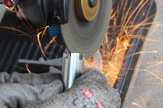
I bought a long 16mm socket to sacrifice, which fits the inner diameter and thickness of the nut quite well. I am going to cut its edges to align with the nut. Once removed, perhaps I should consider replacing it with a regular/standard one.

The socket has to be long to avoid hitting the tip of the shaft. Its excess is a bit more than two centimeters long, plus the tips on the nut, so I need more or less three centimeters inside. This one looks pretty promising.


Here's the fun stuff again. I fitted the grinder on a universal bench tool. It is not really a must have, but this time all I need is another hand. Without it, I would hold the machine with a hand, holding the socket with the other, and would have needed yet another hand for the precise alignment during cutting. No, I don't fancy an angry and heavy angle grinder running on my lap...

Luckily, the socket turned out to be relatively soft. One eye on the crown nut, I started cutting the dents.


Doesn't it look awesome?


I managed to make pretty decent dents. So I even did some finer work on the side edges of the tips to fit better onto the nut.


Not bad at all. It is not a perfect fit, to be honest, but obviously the nut itself is not brand new anyway. I'm sure it has never been removed with a proper tool, but only using the hammer and chisel method. It is not good for the old and tired metal.


Here comes the good old friend WD-40. The nut is almost covered with filth and oil, which is a great combination to jam the nut no matter how hard you try to unscrew it. The cleaner the better.


The output shaft is free to rotate, and obviously I can't unscrew a nut on a freely rotating shaft. So this very simple L-shaped "special tool" aims to hold the output flange onto the transmission body.


Sunday, January 10, 2016

Weather Gods...

As my half improvised special tools served their purpose perfectly, there could be only one place that I had to head to. The metal shop again... 

I've got two important things to do on the crankshaft: to replace the cracked piston arm and to renew the three bearings on the main shaft. The piston arm rolls on a little shaft which is attached tight fit on the crank body. So I simply cannot move it at all. (I don't think I can convince my wifey to the idea of a hydraulic press in the house!)

On top of that, I don't have a proper drift to punch the bearings onto the main shaft.

So to the metal shop. Taking the arm shaft off the crank was a piece of cake for the hydraulic press. I replaced the special rollers below the arm, replaced the three bearings and came back home. I didn't take any photos there - my bad... 

I have already cleaned up and polished the engine block. There isn't a lot to do for the scars of the past half century, but the view after removing all the dirt and oxide layer is lovely indeed.

I tore out the rear oil seal, which isolates the clutch and put in a new one. That's the shorter side of the crank shaft in the above photo.


Similarly, the seal on the engine front cover is replaced. That one isolates the dynamo.

That's where the motor oil circulates, it should never escape through any of these two seals.


The rest went pretty easy... I first heated up the engine body and carefully inserted the now renewed crank shaft into its bed. Screwed new bolts in... 

You can notice the remainings of the metal polish in the photo, that I rubbed rather lousily. It's okay, I'll clean it thoroughy after the assembly is over.


After mounting the main seal cover plate, I'm done with the crank shaft. Or with the front side of it, to be precise...


The camshaft is easier. I heated up the engine body again, put the shaft in and fastened with two screws. 


And screwed the big bolt into the center of the shaft that helps it align.

So I've got just one tiny little obstacle remaining before closing the engine front cover. I'll tell about that shortly...


But before that, lets turn the block over. I put the flywheel on the rear shaft and tighten the big nut. That's the tightest nut on the whole vehicle; the service manual says 170 Newton.meters of torque. (More or less translates into myself jumping on the handle of the wrench, in real world terms) I only managed to achieve about 130 Nm. Well, could have been worse...


As an additional security measure to avoid the nut loosen up, I folded a side of the large washer below it and pulled it as close to the nut as I could.

That's also the last appearance of my "special tool" to fix the crankshaft with the engine body.


Then comes the large clutch spring, (engages the clutch when you leave the clutch lever)


the steel disk, which forms one side of the clutch,


and the clutch pad on top of it, and screwed onto the flywheel with six (brand new) bolts. The clutch is done.


So what's left?

There are two valves on top of the cylinder (four, even five in modern engines) to take in the air-fuel mixture and dispose of the exhaust gas. Their opening/closing timing is critical for a healthy operation, or even avoiding a self destruction.  

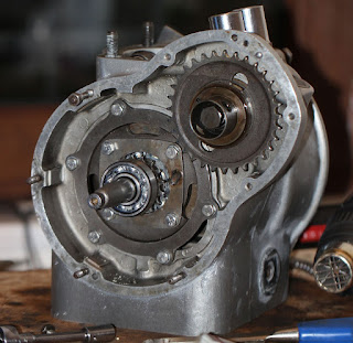
The crankshaft drives the camshaft via the smaller sprocket in the photo, over the cam chain and the large sprocket at the end of the cam shaft. The valves make one full cycle for the piston's two cycles. 

The exact position of these two shafts has to be adjusted very precisely, to achieve the proper valve timing. And it's safer to do it with the cylinder and piston mounted.

Here comes the but - I should have cleaned and painted the cylinder block first! As I cannot play with all those toxic and stinking chemicals (paint remover, thinner, spray paint to name a few) in the house, I should now wait for a good weather in a weekend. Worst case, I will put the engine aside as it is and skip to the gearbox. I have to do that anyway...

At least, this was a pleasing progress so far.