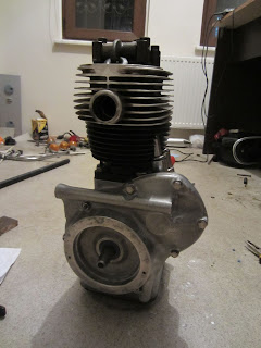
I decided to take my chance with the relatively mild weather last week. It has been a very impatient wait, as this paint job was also blocking my progress on the engine. So I finally took a can of heat resistant black spray paint and painted the cylinder block and the oil pan. Unfortunately it was a bit too chilly and windy, so I cannot call it excellent.
I don't have any photos during the paint, unfortunately. I hurried up to complete the job before the weather gets worse.
Not that bad, really. I waited the paint to dry and carefully hammered the pushrod guides into their slots. I also replaced the rubber grommets.
Then came the piston. You can notice the three metal rings around it. They act as the only insulator between the hot, messy combustion chamber and clean, tidy and oily engine body. They reduce the gap in between the piston and the cylinder wall to virtually zero, therefore the combustion chamber can preserve its high pressure, while the cylinder wall is lubricated by the oil below.
The ring brace in the photo is used for squeezing the piston rings in order to fit the piston into the cylinder.
I put the piston inside the cylinder and tighten the bolt using the provided square key. When it's fully tightened, I carefully aligned it onto the cylinder and slid into it. After a few tries, the piston ended up where it always belonged to.
Using up my brand new gasket set...
Getting here was hard. The following needed to be done at the same time:
- Hold the cylinder head, which is fairly heavy, above the piston rod opening
- Align the piston fitting holes to the tip of the piston rod below
- Hammer the bushing into the fitting holes to fix the piston to the rod
- Put the spring into the end of the fitting hole to trap the bushing
- In the meantime, do not let the piston slide too low to let the rings loose out of the cylinder
- Put the spring into the end of the fitting hole to trap the bushing
- In the meantime, do not let the piston slide too low to let the rings loose out of the cylinder
If you counted the hands needed, you'd have noticed that you'd need more than two for all of these. Luckily, I've got a skilled assistant for such situations.
The top surface of the piston is quite scratchy, but the sides matter more. It should be fine.
Now it's time to fit the cam chain. I think I explained the relationsip between the large "crankshaft" at the center and the "camshaft" at top right of it. The cranksahft moves the piston up and down, while the camshaft opens and closes the intake and exhaust valves. For two full turns of the crankshaft, the camshaft makes one turn.
This is the most critical part of the whole engine - the two shafts must be so aligned, that the valves and the piston is properly synchronized. If not, my best bet will be a weak and noisy engine with too much fuel consumption. Worst (and more likely) case is that many parts of the engine will go beyond any repair.
The valve timings are specified in the service manual in degrees relative to the "top dead center", where the piston reaches the topmost point. I prepared a dial according to the information and attached to the center of the crankshaft. It needed a couple of tries until I get the correct synchronization.
I attached the chain clip and then screwed in the chain tensioner and its spring that I bought recently in Germany. (just behind the crankshaft in the photo) This is not part of the original design, but rather an improvement introduced with the later model R27 - and completely backward compatible with R25, too. I mentioned about the old slack chain having damaged its surroundings, now I feel better with the tensioner.
After oiling the paper gasket, I closed the front cover with brand new bolts as usual.
I can close the cylinder now. Putting its new gasket, I put the header block and place the cams on their places. The camshaft has two "rockers" which control opening and closing of the intake and exhaust valves by pushing the cams via the pushrods. One side pushed up, other side of the cam presses the valve down and frees up the flow.
Last but not least, I have to adjust the valves. There needs to be a small gap in between the "horn" on the cam and the valve, in order to operate properly. Too loose and the valve cannot open wide enough. Too tight would possibly damage the valves, cams, pushrods, camshaft, in whichever combination that Murphy Law finds most suitable. The service manual says, the intake valve gap should be 0,15 mm and exhaust should be 0,20 mm.
The adjustment is simply made by screwing a bolt in or out and securing with the nut on it. In the photo, the 0,15mm thick feeler gauge can fit into the exhaust side gap, while the 0,20mm almost can not.
The engine hasn't looked so complete since many months... I didn't close the valve covers, the holder piece needs to be cleaned with sandpaper and possibly painted. After painting the generator body in heat resistant silver, I'll mount and adjust the electrics. Then comes the transmission.
Is that the faint light at the end of the tunnel?
Is that the faint light at the end of the tunnel?


No comments:
Post a Comment