Saturday, September 29, 2018

Happy-ish Ending

I'm being way too optimistic here.

It's been literally years since my last update here. Not that I lost interest or something, on the contrary, simply because I could hardly spend merely a handful of net days on the work in the meantime. And this is going to be a bland overview of those days, without any significant entertainment.

Last time when I left the Beemer, I had successfully stopped the oil leaks (to a great extent, I should say) and tidied up the cabling and connections. Now is the time for the grand opening! Well, that was two years ago, actually. Ready for the engine start!

So, did it? Of course not, how come can you think that I'm that lucky at all! During "both" those years, I've been investigating and researching about my mistake, where it could lie, what I could have done wrong. Finally I have the answer - so elementary!

Let's review the potential failure elements. After all, there are only three basic variables that make a combustion engine run: if there was something wrong with the caburetor (fuel feed) it would have been obvious to the visual inspection. It could have been something with the electrics (spark timing) but I learned a lot about it and I'm fairly fit dealing with it.

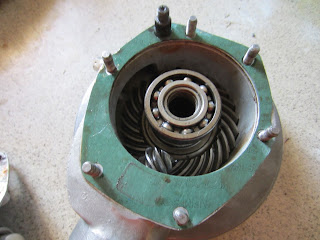
There remains only the cam timing, which makes sure the air-fuel mix gets into the cylinder and exhaust gas after the ignition gets out of the cylinder at the right time - that is, when the piston is at the right position. The cam timing is not something you're supposed to adjust; it is one of the key parameters specified during the engine design. In straightforward terms, the crankshaft, where the piston is attached to (the large shaft and its sprocked below the ball bearing in the photo) and the camshaft (larger sprocket) have only one correct position relative to eachother. The camchain in between maintains this relative position, provided that you pay extreme attention, take multiple measurements and set it correctly when fitting it. Or else!!!


Running out of ideas, I decided to check the cam timing one last time. Opened the valve cover on top of the engine head, watching the "Top Dead Center" mark which is conveniently visible on the flywheel through a small hole on the block, started carefully rotating the crankshaft by hand and waiting for the valves to move. The time is measured in crankshaft angles, and it is well specified which valve opens at what degrees.

Well, here comes the disaster! The valves are almost 45 degrees too advanced! The crankshaft sprocket has sixteen teeth, therefore we have 360/16=22.5 degrees per tooth. This means I am off, not by one tooth but two! How careless, how stupid, how come I didn't notice that at all! 

So I removed the engine block, opened the front cover, removed the cam chain and reattached at the right position. After several measurements to make sure I got it right this time, buttoned the engine up again and brought the poor old Beemer back together. These two sentences took me about one full day.

I've got a new and fully charged battery. Revisited the ignition timing, that looks good, too. I even found a couple liter of gas in a jerry can lying at the corner - definitely a year old or two, stale and smells a bit foul, not ideal but should pull off anyway. The cylinder walls must be bone dry, I dripped a few cl's of engine oil through the spark plug hole, to help reduce the friction and improve the isolation of the chamber by sticking between the piston rings. Turned the ignition on, twisted the throttle a little, started kicking. After a few kicks, coughs and sputters, came a huge puff of blue smoke (that's the rest of the oil I dripped burning away) and it STARTED!!!

Started but shaking like an old washing machine. No wonder, that is due to my negligence, too. While I took the engine apart, I renewed the cracked connection rod and the bearings on the crankshaft, and just roughly had it pressed again and convinced by just an eyeball estimate. If you are talking about a cast iron mass of few kilos, rotating several thousand times every minute, that is definitely not the way to go. You should instead make absolutely sure that the rotating axle is properly balanced within the specified tolerance, which is, according to the official documentation, two hundredths of a millimeter! About thickness of a hair, for a real world example. Anyway, the way ahead is much clearer now, at least I know what it takes to reach this point.

Well then, what now? Hadn't I moved abroad, I would have long since bought a few important tools I was considering for a while and had a proper amateur workshop. But under current circumstances, there is no light yet in the tunnel. It is not realistic to keep working and expect anything reasonable at the rate of roughly a few days per year. I do hope that I will some day eventually bring together the little workshop here, and the first thing I'll do then would be to transport the little Beemer over here. Unfortunately it is way too early for that.

All I can do now, is to give my apologies to my Old Beemer and put an end to our journey. Looking back, beside all the new-to-me technical skills and knowledge, I have learned many lessons and dusted off a lot of information and wisdom about engineering discipline and about life in general. That is all I have earned anyway, otherwise it's been an endless money pit - worth every penny.

I'm already looking forward to carrying on with the work!

Monday, September 19, 2016

Erase and Rewind...

So you thought it was just as simple as pushing the fast forward button and that's it? No sir, you're wrong... Quite badly...

Our reunion after about two months was not that promising at all. I am not caught by surprise, though - the last couple days before my departure already gave me a hint about how I was going to find the Beemer on my return. So I am well prepared.

Let's take a look at the engine first. It already started leaking, and I just hit bull's eye with the ice cream box (my favorite one). Not a single drop outside. 

Obviously, at the beginning, the roughly 1 liter of oil in the box was IN the engine. That means, not much is left in the engine from the actual capacity of 1,25 liters.

We'll get back here. Now let's move on.

Final drive is the next stop. It too was dripping and awarded a box - unfortunately not ice cream this time. Wish I had even more of it when I had the chance... 

If I remember correctly, the final drive takes around 200 ml of oil. This means, it's drained completely, too. But into a spot on box again!

Not over yet...


Now, this was a bit unexpected... See the puddle under the wheel? The right side fork has a leak, exactly where it should have been sealed by the rubber ring. This needed a box as well.

Anyway, I think I's better clean up the mess first...


Don't look for exotic causes for the leaks; it all comes down to the old Beemer being old! Let's get back to the engine for a closer look.

But first I need to make up some space below the oil pan. I don't want to lay the bike down entirely, so I carefully gave it a comfortable lean on the couch with a metal frame and rather stiff filling. Should do the job well.
I removed the oil pan. You see the bolt holes, the two on the top right in the photo (that is, front right corner of the engine) are worn. The engine is made of aluminium alloy, which is a soft compound. Screw the bolts too tight or skip the grooves just a couple of times and that's enough to ruin the holes. Given 62 years of lifetime, it's quite likely.

One solution would be to remove the engine completely or somehow take the entire bike to a specialist...

But here is my solution - the Helicoil kit. I was useless with taking photos, so you'll need to bear with my explanation instead.

First of all, you drill the bad hole with the provided bit, which is just slightly bigger than the hole diameter. (Not in the photo, it was already attached to the drill, I guess.) You need to keep it aligned or make things worse. That's why I leaned the bike over the couch, I needed room for the drill.

After that, you groove your new hole using the provided guide. This can be tricky, too. You need to align it well, especially at the beginning. The rest is easy.

One of the steel inserts in the photo above will be screwed into the hole using the tool looking like the number 7. They have a little extension to sit into the slot at the tip of the tool. When it gets into the right depth, you simply snap that extension with the straight tool. Here is our new bolt hole...

And even stronger than ever. I had another broken bolt in the wheel hub, now that I get hold to the Helicoil, I fixed that, too. The photo is from the drilling stage. 

I think that's a good explanation why I didn't take proper photos. Because it's so much fun, fixing bolt holes with this little smart toolkit. I know that doesn't sound mentally very healthy...


The result is good, though, isn't it?


Now to the final drive. Compared to my first attempt, this time it was child's play to remove and split it apart...

Nothing visible. I guess it's just tiny little scratches and impurities piled up on the mating surface that lead to a leak. 

Carefully removing the paper gasket, I sandpapered the surface using a small wooden block to support.


And in addition to that, I applied a thin layer of liquid gasket. It's a toothpaste like red paste (don't know why I bought red, it had other colours, too) sold in a tube, once it gets into air it becomes like rubber in a short time. 

That much should do the trick.

By the way, the engine oil pan had its share of the liquid gasket, too. 


I'm still not sure about the front fork. I removed it and sandpapered the sealing surface inside of the chrome stanchion, supported the sealing surfaces below the screws at the bottom with some liquid gasket and that's all. If the stanchion is bent or scratched significantly, I won't be able to stop leaking without replacing it.

We'll see that in time, but now I've got more serious stuff to do...


Tuesday, August 9, 2016

Fast Forward

I admit beforehand that this will be probably the patchiest part of the whole blog. As expected, it all got totally hectic with our decision to move abroad. On top of that, witnessing that the beemer is slowly getting into the shape, way prettier than it used to be, I simply got full throttle with the progress, let alone thinking of taking photos.
Let's get on foot again. Logically, starting with the center stand. I should start in a smart way while it's still light enough to push and pull it around, the only reasonable way to go is bottom-up.

Next step, front forks and wheel. Thus, once attached, I will have a tripod together with the center stand, that will carry the weight.

Compared to all the mess during the removal, putting it back together feels like child's play. Let's begin with fixing the upper half of the forks to the lower clamp. The stanchions are fresh from chrome plating, aren't they shiny?


This can get tricky. At the beginning, I wanted to replace the steering head bearings with a modern tapered roller bearing, but I didn't dare remove the old style bearing seats. Instead I just bought new 0,5 mm diameter balls. With a generous lump of grease, I carefully place the balls into the lower bearing seat. I like grease...


Same goes to the upper bearing. Now it's time to fix the  steering head into place.


I skipped the front forks, but they were merely three "pipes" inside eachother, held together by a pair of nuts. After that, come the headlight mounting plates, upper fork bridge and fork springs. Then I loosely fit the front brake drum and the wheel into place. The Beemer is proudly standing again!


A historical moment! I think I'm getting old, I exhausted to death while holding and aligning the engine, weighing roughly 30 kilograms, into its seat. After that, it needs just the two bolts to fix it into the frame.


I can't express enough, how lean and simple the Beemer is, both aesthetically and technically. After fixing the powerplant with just two bolts, now I'm attaching the transmission to the engine. Just four more nuts to go... Right after that comes the carburetor.


Proceeding to the rear end. Left shock absorber and the final drive, integrated to the right shock absorber were waiting for their turn for a long while. Aligning them in their place with one hand, I push the center bar that fixes the whole assembly down from the upper clamp. It sits in its place after a couple of mallet hits.


Now a good deal of fast forward. I attached the rear fender and wheel, then removed the front wheel and attached the front fender. The bike is so finely designed, that when you remove the front wheel, the center of gravity sits onto the rear wheel, and vice versa. The tank needs just another two bolts. That's all, really...
The seat is cool, isn't it? At first, I was considering renovating the old double seat. I'd have needed to tear it apart, clean up and protect the rusty frame, have the missing springs manufactured, have a brand new upholstery and foam filling. Well, what's left? So I decided to throw the old one away and bought a so called "Pagusa" single seat. Pagusa, by the way, stands for "Patent Rubber Seat" in German - they patented the seat in 1935 and also licensed a few other manufacturers up until sixties.

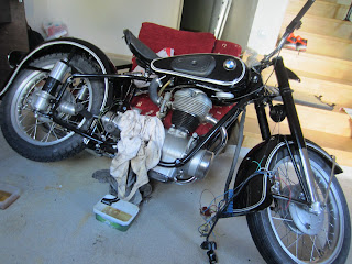
Here comes the answer to the million dollar question - will the Beemer resurrect after all that it's gone through? I'm afraid I don't know the answer yet. I put the wiring loom, but ran out of time to put the headlight and the ignition plate together. The Beemer is waiting for my next visit exactly the way it is in the photo above, needless to say, I'm looking forward to seeing the happy end. I guess we'll need to keep patient for a month or two...

Friday, July 15, 2016

Pinstriping 101

The paint job is finally over. It was not just the large parts, but every single metal part (maybe 25-30 of them in total) now has a beautiful glossy deep black. Furthermore, all the chromed parts are newly plated and shining like a mirror.

But the most important part of the entire project (I hate calling this restoration work a project) is still not done: the pinstripes on the tank and the fenders. I had made a thorough research in the net, there is a lot of material and information. Interesting to learn, the original pinstripes are drawn as the last step, without any additional layer on top. Even more exciting was that they used to be drawn freehand, without any support. I find it so special, perhaps the final defense line against process automation. Therefore, the width of the lines were never the same, no two BMW's were ever identical. What makes them flawless is the little human flaws in them. I am definitely not that insane to draw them freehand, I'll use masking tape!

Nevertheless, I do not have the tiniest talent for such fine work. Yet, I was determined to do it for whatever it takes. A good quality masking tape for parallel lines with the right size, and a special pinstripe brush that I bought online from England have been waiting for their turn for a long time anyway. I found a good car paint retailer to mix the correct colour called creme white, code RAL 9001. I already have paint thinner. So the last step is to persuade the wifey to draw the lines. It was much easier than I expected, I guess she was way fed up with this mess and hoping to complete this mess as soon as possible. Anyway, I don't question how, but she accepted to take over the trickiest yet the most precious step of the entire restoration work.

Here we start with the masking. I really liked the tape a lot. It's very strong yet elastic enough, the adhesive is also very fine and durable. I was wise enough to order two rolls of 17 meters each, so I've got enough material for trial and error until I get used to it. The rear fender is the right place to start, after all, only here the pinstripes end at the edges.


The tape has two layers to deal with. First you peel off the bottom layer and with a careful tension proceed all the way. The trick is to maintain a slow but steady "peel-pull-stick" rythm, then it becomes very easy to follow the nice curvature of the fender.


Once that's done, you remove the top layer. A blade tip comes pretty handy to peel it off.


What remains is the middle layer, that is, the three lines of masking tape with fairly homogenous distance in between. Straightforward...


Hell no, it's anything but straightforward! The real trouble comes with the front fender. Rear was rather easy, but here it's almost impossible to follow the tight corners while keeping an eye on the overall alignment. It took us some creativity, a bit of dexterity and just a small pinch of lousiness to get it done. It was not easy at all!


This is the way the front fender ended up. We were so focused that I didn't even think of taking a photo of the tank during the work. It was perhaps even harder than the front fender, especially the rear curve was very sharp, there are no reference points to align the stripes and it's the most open and eye catching part of the bike, so no room for carelessness.

Time for the actual paint job now.


You should consider yourself lucky for not seeing my Neanderthal hands instead. Apparently, my full time wife and part time photographer/assistant is a natural born painter! We mix some paint with just enough thinner in a small jar. It's important to gain a good feeling here, as the thinner evaporates very quickly and all of a sudden the mixture thickens and needs some more thinner. If it's too thin, you cannot feed the right amount of paint onto the brush. Too thick and it leaves tiny little bubbles on the surface as you draw. You should keep the right thickness and maintain a steady speed with the brush. It's all about patience and precision.

The tape saves you if you lose control of the width, but the thickness of the paint layer must be as consistent as possible. That translates to a constant angle and distance of the brush against the surface. We apply two rounds of rather thin layers on all of the stripes. Here you can also see my painting desk is not less messy than the rest of the entire place.


Here is how the painted rear fender looks...


And last but not least, the tank.

The only thing remaining to do is to wait for about half an hour to allow the stripes to dry and peel off the three masking tapes. Voilá - your brand new pinstripes.


All right, I admit that if you take a close look, you can figure out both edge and paint thickness faults here and there. So what, we attempted the most challenging work of the entire restoration together and the result is just perfect! Any objections?


Thursday, July 7, 2016

The Wheels...

It's been quite a while since I did this but I can only now find the opportunity to write as in the meantime we moved to Germany. Isn't it funny, the old Beemer, born here in Germany, is sitting in Ankara, where I, born in Ankara, am living now in Germany, only about 400 kilometers away from its home town...  

Anyway, so with the transmission, I'm done with all the significant work on the bike. Still, the wheels haven't been touched yet. I must overhaul them and clean up the dirt - and what a mess indeed! Here we go, as usual, with plenty of WD-40, brake cleaner, sheets, sandpaper and much more...

I begin by removing the four bolts holding the aluminum hub cap and look at the mess! And look at the poor old roller bearing. No surprise, some of the bearing balls were scattered already when I first removed the wheel. And not a big deal, I've got brand new bearings waiting for the duty.

I am not able to name every single substance gathered here over years to become this slimy dirty layer here. How can I get rid of that! 


Removing the bearings out of the wheel hub was pretty straightforward using the hammer and drift. We've got two bearings, one of them is a ball bearing, and the other is a "needle" bearing. Both are dead, you can see the needles in the previous photo, they should have been sitting in their seat in the bearing. Between the two bearings, there are two metal spacers to keep the distance between them. In the photo you can hardly see them because of the greasy dirt.


Here you can see better. From left to right, needle bearing, spacers, one inside the other, ball bearing and the hub cover. And next to them, the brand new bearings still waiting.


This is the best I could do. Steel wool, brake cleaner, sandpaper, even some gasoline, over and over and over... No, I can't make it any better.

The real issue is the spokes. Normally, I should have removed them all, either sanded and cleaned them, or even better, used a new set to mount. Unfortunately, spoke adjustment is a very difficult precision work, requiring special equipment and experience. Neither can I do that on my own, nor is there any specialist here that I know of. Therefore I only sanded them in place, as good as my poor and now wounded and aching fingers fit.

For some reason the other wheel looks much worse. Same operation for it, too...


Then it's time for the new bearings. Easy work, heating up the hub, I simply drop the first bearing inside. Just a couple careful hits with the hammer over a socket with the same outer diameter (never hammer the loose end of a bearing, in this case the inner ring, otherwise you risk damaging it.) and it sits into its slot.

You can see a lot of grease in the hub, around and between the bearings and spacers. These two bearings carry the entire weight of the bike and the rider by themselves, and they are always moving. Grease is never more than enough...

Here comes the second bearing.


Look at the "before and after" photo I took after cleaning up the first wheel, not bad, eh? Not perfect but the difference is significant and looks good enough if you don't examine too closely. And even this much cleaning took me numerous hours over several days. On top of that, of course I replaced the tyres and tubes with a cheapo set.
Frankly, I don't have much left to tell after this, just a few notes about painting and that's it, really. The Beemer is in a much better shape now, I think I shared a few photos on Instagram (lazy man's social media) about the progress. Bringing all the parts back together took almost no time at all, and obviously I was so stunned with the progress that I hardly took any photos of it. But the real question is not answered yet: Can the 62 year old machine wake up from its long sleep and walk again?

Thursday, April 28, 2016

Last Stop

I feel that, in time I've gotten to proceed faster and with more self confidence. Wish I were able to be like this at the very beginning, but I believe that was the price to be paid - with a lot of time, reading and trial-and-error. 

Out of the three main systems, the final drive was the first to go. As I sorted out and closed up the engine block, and waiting for the rest of the parts to be painted, it became totally inevitable to move on to the transmission. After all, it has been sitting and waiting for my attention with extreme patience for more than a year now.

I hope you read about my disappointing "special tool" attempt to remove the centre nut of the output shaft. After a few more failures, I decided to go old school. Once again, using plenty of hot air, a hammer and chisel, I made it move. The rest was straightforward.

I had to go ahead and finish this up!


Next stop was the output flange. The engine output is transmitted over the shaft via a rubber "puck" between two identical flanges, this one and the one at the very front of the shaft. The flange sits on the shaft as a tight fit, so I need to find another trick to pull it off.

I tried with my cheapo puller first. Obviously didn't/couldn't work. Then a few more attempts mistreating my high quality bearing puller, which single handedly sorted out the entire engine block. That didn't work either - it was not a proper fit anyway. 

Lesson learned (again and again) - there is just one method and tool to do a job. Without the proper tool, you can't do it. This time, the lesson cost me a decent two armed good quality puller.

Can you notice my brand new "special tool"? The flange is designed for the rotational forces, but it can't bear the pulling. You can find examples of "folded" flanges in the internet. Therefore I supported it with a 22mm and two halves of a 20mm nut to resist bending. It was almost a perfect fit between the two tips.

Having fixed the puller behind the tips, I started rotating the puller bolt. It is an extremely stressful process, especially with all those squeaks and cracks coming out of the parts. It's always possible that another weak point could give up and bend or break instead of the puller breaking loose.

After a few careful turns, with a loud, metallic noise resembling a glass shattering, the flange finally got loose. 

That's it!

I don't expect any big blocking points anymore, but obviously a very thorough cleaning job  is awaiting me. And my brand new bearings and oil seals are ready. 

First, let's get rid of the nuts that are holding the cover. No, not that easy mister!


There are three bearings sitting inside of the cover. In order to get them loose, I needed - guess what - hot air again. At around 70-80C, the aluminum material expands just enough to give way to the steel bearings, which expand less.

No surprises inside. Plenty of dirt and mut leaking through the old seals, remains of old oil and six bearings one of which is shot.

Similarly, the rear (actually front) ends of the three shafts have bearings fitted to the transmission body. Again with enough heat, I got the shafts out of their beds.

There remains the gear shift mechanism. It's a very simple, compact yet very intelligent design. Let me try to explain...

The short shaft extending towards outside is attached to the gear shift pedal there. The circle next to it is for properly positioning the gear selectors.

Unlike cars, the bikes have sequential gearboxes. You can select 1, neutral, 2, 3, 4, etc. from bottom-up. You can only switch to the adjacent gears by strongly pressing the pedal upwards or downwards.

When you press the pedal, a fork rotates the selector circle a few centimeters. You can see the notches below that - they set the proper gear positions by sitting onto a metal tip. Currently it's in neutral. 1st notch is just to its left and 2, 3 and 4 are to the right. Simple, isn't it?

Here are the input and output shafts and the gear pairs for 4th, 3rd, 2nd and 1st from left to right. Output shaft (bottom) gears can rotate freely.

Two railed disks on the output shaft can move along the shaft. They have "dog teeth" pointing outwards on each side, so they can slide and attach to the desired gear and in neutral, both disks rest in the middle. If they ever attach to two gears at a time, you would simply smash the transmission. The gear selector circle avoids that with two properly positioned grooves on it.

The rest was easy... I washed every single part twice, pulled off the old bearings and fitted new ones, renewed the oil seals on the input, output, shift pedal and kickstarter shafts. Again heating up the cover, I then fit all three into their positions (you can't do it one by one) and heated up and closed the cover with the help of my rubber mallet.

While cleaning, I also sanded off the dull and rusty layer outside of the transmission body and treated it with metal polish.

It shouldn't be that difficult to fit the flange back onto the output shaft and attach the awkwardly shaped castle nut.


The rest should come easy...